 |
 |
 |
|
| Annex 1 | |||
| 4.5 Interface DFM-CFM |
 Contents Contents
|
|
|---|
 1 Characterization of the Interface
The basic method CFM - Control Flow Modeling is an upgrade of DFM - Data Flow Modeling with regard to realtime applications, i. e. CFM requires the existence of data flow diagrams (type "direct integration"). In the graphical representation of flow diagrams this is possible in two different ways /Hatley, 87/:
- The components of the control flow modeling (control flows, control stores, control bars) are drawn into the data flow diagrams which results in the so-called flow charts.
- Separate control flow diagrams are generated by deleting the flow charts in the data flow diagrams and entering the control flow components instead.
The data flow model and the control flow model express a different point of view: while in the case of the DFM both the data flow structuring and the identification of the data flows are dominant, CFM illustrates the way the processes are influenced by the control flows. In this case, however, the CFM only lists the structural context while the control specification describes the exact effect (see 4.14 Interface CFM-STM).
 2 Example

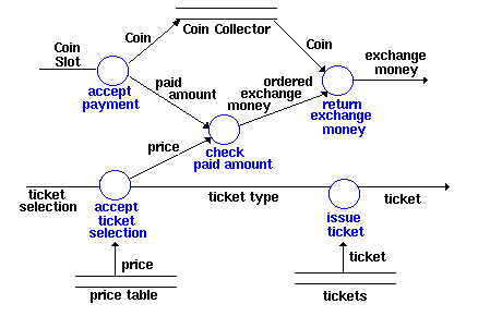
Figure 4.6: Example Data Flow Chart

Figure 4.7: Example Control Flow Diagram
Explanation:
The data flow diagram (Fig. 4.6) describes the basic functioning of a ticket machine. The example can be represented in one single diagram without further detailing levels. The data flow diagram illustrates which data are processed by which processes; it does not illustrate, however, the way a ticket is bought. The sequence of activating and deactivating the processes for purchasing a ticket is illustrated in the allocated control flow diagram (Figure 4.7). The control flow diagram contains the same processes as the data flow diagram. Instead of the data flows, however, it also contains control flows and control bars. Control flows between a process and a control bar initialize the actions depending on the system state. The initialized actions have the effect of making one or several processes active. This connection is explained in the control specification (see 4.14 Interface CFM-STM). The initialized actions are represented by control flows between a control bar and a process. The mechanism of the control specification is better explained in the 4.14 Interface CFM-STM. 3 Tool Support
The separate or respectively combined representation of CFD's and DFD's, the change of aspects, and the consistency check between the different diagram types are generally performed by tools that are supporting SA/RT - Structured Analysis with Real-time-Extensions modeling.
 4 Literature
| /Hatley, 87/ | Includes several examples about realtime modeling in section VI. |
| /Raasch, 91/ | Chap. 5 explains the interaction of the components by means of examples. |
 |
 |
 GDPA Online
 Last Updated 01.Jan.2002 Last Updated 01.Jan.2002
 Updated by Webmaster Updated by Webmaster
 Last Revised 01.Jan.2002 Last Revised 01.Jan.2002
 Revised by Webmaster Revised by Webmaster
 |